Installing the Software
The first step is to install the network computer software on one or more hosts. The network computer plugs directly into the network, so you can install the software on one host or distribute it across different hosts on the same network.
The media contains all of the files you need to boot and configure your network computers. With SETUP.EXE, you can install everything or select only the files you need for your environment.
This chapter provides a quick-start list. The chapters that follow present detailed installation information.
Quick Start
The following steps provide an overview describing how to install NCBridge on the host and to configure an NC for operation. Details can be found in the remainder of this manual. Also see the NCBridge Reference Manual for more information.
NCBridge Installation
- Log onto installation host.
- Double-click on the My Computer icon on the desktop. An icon representing the CD-ROM should be present.
- Insert the CD-ROM with the NCBridge software into the drive of the host.
- The NCBridge installation wizard should begin to run. If not, select View > Refresh and then double-click the NCBridge CD icon.
Follow the on-screen instructions for installation.
NC Terminal Installation
- Unpack the NC hardware and assemble it as described in the Installation Guide provided.
- Turn on the NC.
- When the boot screen appears, press the spacebar.
- Set the following items:
IA <IP address of NC>
IH <IP address of boot host>
IM <subnet mask>
BP </destination_folder/tekxp/boot/os.900>
IGate <IP address of gateway host>
NVS (to save settings in NVRAM)
B (to start boot process)The network computer should boot for basic operation. Make custom changes to the installation, as desired.
Media Contents
The directory hierarchy is created relative to the destination folder. If the destination folder C:\NCBridge was selected at installation time, all files and folders are installed in that location. The tekxp directory is also created under the destination folder.
Throughout the NCBridge manuals, the install directory is assumed to be tekxp. Here are the tekxp directories:
- tekxp\bin\nt contains network computer utilities for the NT environment.
- tekxp\boot contains boot files, fonts and clients. Files that differ between models use a .model suffix. Refer to Table 1-1 for model information.
- tekxp\boot\config contains the network computer configuration files.
- tekxp\boot\fonts contains the supplied non-resident fonts.
- tekxp\boot\<language_directory>\app-defaults contains translated text for network computer clients.
- tekxp\examples contains examples such as Xsession and bootptab.
- tekxp\man\nt contains man pages for many of the included utilities.
- tekxp\mgmt contains a sample SNMP MIB file.
Running SETUP.EXE
These steps tell you how to perform a basic installation of the NCBridge software on the Windows NT host. For details about customizing the software, refer to the NCBridge Reference Manual, supplied on the Documentation CD-ROM.
Getting Started
- Log onto the NT host where you are going to install the NCBridge software.
- Open the My Computer icon by double-clicking it. This displays icons representing system resources, including the CD-ROM.
- Insert the NCBridge CD-ROM into the drive. The CD-ROM device icon should be replaced by the NCBridge icon (the drive label should say NCBRIDGE_VERSION_ 4_0) and the installation wizard should begin. If this is not the case (and the NCBridge installation program does not start), select View > Refresh and double-click the NCBridge icon.
- When the install programs executes, the NCBridge splash screen appears and the install wizard software loads. A Welcome dialog appears. Click Next on the on the Welcome dialog to proceed. Click Cancel at any time to abort the installation.
Setting the Installation Path
When the installation process begins, the Choose Destination Location dialog shown in Figure 1-1 appears. The Choose Destination Location dialog allows you to set the desired installation path. By default this path is C:\NCBridge or the existing NCBridge installation path. Clicking Browse brings up a file selector, shown in Figure 1-2, to help you navigate though your file system for a suitable destination location. Once the destination folder is set, click Next to proceed. You can revisit previous install dialogs by clicking Back.
If you have a current installation, your configuration files are saved for you. Be sure to check the new configuration files for any new commands, and add any applicable commands to your saved configuration files.
Note: If you change the destination folder for installation, ensure the new path matches the Secure Read directory specified by the NCD TFTP applet, displayed in the Control Panel. If there is a previous installation in the current directory, the configuration files (.cnf and .tbl files) are preserved. The new configuration files are stored in the directory <destination folder>\tekxp\config_date where date is the format YMDHMS.
Next, the Font Server Query dialog shown in Figure 1-3 asks if you want to use a font server.

If you indicate that you want to use a font server, the Font Server Specification dialog shown in Figure 1-4 appears.
Enter the IP address or hostname of the font server and the port number in this dialog and click Next.
Selecting Installation Options
In the Setup Type dialog shown in Figure 1-5 you can choose between three software installation options:
- Full installs with all options. Recommended for most users.
- Compact quickly installs only those files necessary to boot and configure NCD network computers. These include the network computer boot files and configuration files. This is good for upgrading existing NCBridge installations.
- Custom allows you to choose specific packages for installation. This is recommended for advanced users. This installs only the options you select. By default, all options are pre-selected. To make your selection, click Custom and click Next to access the Select Components dialog.
If you select the Custom install option, the Select Components dialog shown in Figure 1-6 appears. A list of software components is shown with check boxes indicating the desired selections. Some components are comprised of subcomponents which can also be custom configured. Highlight a component and click Change to access subcomponent lists. If the Change button is disabled, then the component you have highlighted does not contain a configurable subcomponent list. After selecting the desired components for installation, click Next to begin the file transfer process.
If you select Compact Install or Full Install, the next dialog that appears lets you verify your installation settings before the installation begins. The Start Copying Files dialog shown in Figure 1-7 displays the setup type, destination directory, and font server settings. If the settings are not what you want, click the Back button to return to the Select Components dialog so you can change them.
If the settings are correct, click Next to start the transfer of NCBridge software from the CD-ROM to the destination directory on the server.
Installation Dialog (during the File Transfers)
The screen displays three file system status bar meters and a dialog box with a status bar. The status meters on the left indicate the transfer status of individual files, installation completion status, and overall disk usage. The status bar in the dialog window indicates the percentage of the installation completed.
Installation Completion
When installation finishes, the Setup Complete dialog shown in Figure 1-8 appears, stating that the installation of the NCBridge software is completed.
This dialog asks if you want to start the NCD TFTP service. For more information about the TFTP boot method, see the Boot Methods topic on page 2-5. Click the checkbox to indicate whether you want or do not want the TFTP service to start at this point, then click Finish to exit from the NCBridge installation program.
Removing or Modifying An NCBridge Installation
The Welcome dialog shown in Figure 1-9 provides a convenient way to add, modify, or remove components of an existing NCBridge installation. To start the process, click Start > Settings > Control Panel. Click the Add/Remove Programs icon and select NCBridge from the list of installed programs. You may need to insert your NCBridge Installation CD in the CD-ROM drive.
- Select Modify if you want to add components or remove currently installed components. The same dialog used during the original installation, the Select Components dialog (shown in Figure 1-6) appears. Indicate how you want to modify the NCBridge installation by clicking on the checkboxes to select or deselect the components you want, then click the Next button and the reinstallation process will proceed.
- Select Repair if you need to reinstall NCBridge.
- Select Remove to uninstall the NCBridge software.
Getting Acquainted
This section describes adding the first network computer to your system. It contains step-by-step procedures for performing a basic network computer installation. Follow the instructions in this section to become familiar with the network computer's network configuration parameters, Boot Monitor, and Setup utility. In addition to learning about the network computer, the procedures presented in this section lead you through the basic host configuration procedures for supporting network computers.
Note: If you are familiar with network computers, skip to Chapter 2, Making Choices, for information on integrating network computers into your system. Basic network computer installation requires these steps:
- Configuring host files to support the network computer.
- Collecting information about your environment which is needed to boot the network computer.
- Using the Boot Monitor to enter network computer communication parameters and establish a host connection.
- Logging in through a Telnet session from the Client Launcher.
- Using Setup to enter the network computer configuration parameters.
After the basic network computer installation is complete, the network computer is able to:
- Locate the host on the network.
- Download the operating system, configuration, and font files.
- Apply configuration files residing on the host.
Basic Installation
In a distributed computer environment, host computers perform a variety of functions. The boot_host sends the boot_file to the terminal, allowing it to function as an X display. The font_host contains the files defining the appearance of the various character fonts that can be displayed by the network computer. The network computer needs access to this host frequently in the course of a user session. The login_host is the host where the user's login account is found. The login host supplies a login window to the network computer, using some utility that provides login services.
Here is an example showing information about a sample environment:
Boot Host: Compaq Proliant running Windows NT
Boot Host Name: oregon IP Address: 128.07.60.01
Network Computer Model: N916
Network Computer Name: portland IP Address: 128.07.60.30
Netmask: 255.255.255.0
Gateway Address: 128.07.60.100
Broadcast Address: 128.07.60.255
Boot Method: tftpIf you are not familiar with the listed terms, consult your Windows NT System and Network Administration manuals.
For the examples in this section, it is assumed you have loaded NFS on your Windows NT system, and have enabled a mount point to the network computer information. Refer to your NFS manual for more information.
Network Computer Worksheet
Complete this worksheet prior to powering on the network computer. When completed, the information on this worksheet assists you in booting the network computer and performing other procedures.
- Network computer model: NC_____
- Network computer hardware address: ____:____:____:____:____:____
- Network computer name: _____________________
- Network computer IP address: ____._____._____._____
- Boot Path: _________________________________boot_directory
- (/<boot_directory>/boot/<boot file> For example, /tekxp/boot/os.900)
- Use Table 1-1 to determine your boot file.
- Boot Method: tftp
- Subnet mask: ____._____._____._____ ip_subnet_mask
- Boot Host:
a. Host name: _____________- Gateway on the network computer's subnet: ____.____.____.____
Configuring Host Files
This example shows how to configure the nfs (Network File Service) host utility to provide booting service.
Enabling NFS Access
In this example, NFS is used to download the network computer operating system, X server, configuration files, and resident fonts.
- Add the boot_directory (/tekxp/boot) to be exported on the host. Export as read only. Refer to your NFS documentation for information on the name and location of the exports file.
- Edit the \%SYSTEMDRIVE%%SYSTEMROOT%\system32\drivers\etc\hosts file and add the network computer name and address.
- To enable the mount point immediately, open the NFS > NFS Server dialog. Click on Exports. Use the Add button to add and verify mount points.
- Open Main > Services to verify NFS is running.
Powering on the Network Computer
Verify the physical installation of the network computer's cables, power cords, keyboard, mouse, and network connection with the pictorial installation sheet included in the packing box.
Turn on the network computer's power switch. On the first power-up, you must specify the keyboard you are using. The North American 101/102 or VT200 is selected by default (depending on the connected keyboard). Press Enter or Return to accept this keyboard. For a different keyboard or nationality, press the Spacebar to scroll through the list of available keyboards and press Enter or Return to select the appropriate one.
After specifying the keyboard, press the Enter or Return key again to display the BOOT> prompt.
The BOOT> prompt indicates that you are in the Boot Monitor. The Boot Monitor is a simple, command-line utility that provides an easy way to input boot commands. These boot commands set the parameters which describe the network computer in your network environment.
The scoreboard is an area in the upper right-hand corner of the boot screen. At this time, the scoreboard shows only default values. Use the scoreboard to verify the entries you make in the steps that follow.
Booting the Network Computer
To enter a boot command, type the command and its associated parameter after the BOOT> prompt. To complete an entry, press Enter. To see a list of the Boot Monitor commands, type help and press Enter.
Note: An "unrecognized command" error message and description appears on the screen if an invalid command is entered. The line numbers in the steps refer to lines on the network computer Worksheet (page 1-15) where you filled in the appropriate information. If you have not completed the Worksheet, do so now.
Using the Boot Monitor, perform the following steps:
- Use the iaddr command to enter the network computer's IP address. (See Line 4.)
- Use the bpath command to enter the boot path. (See Line 5.)
- Use the imask command to enter the subnet mask. (See Line 7.)
- Use the ihost command to enter the boot host's IP address. (See Line 8b.)
- Use the igate command to enter the IP address for a gateway host if the network computer is booting through a gateway. (See Line 9.)
- Use the bmethod command to specify TFTP as the boot method.
Note: Check the scoreboard to verify your entries. If there is an error, re-enter the command using the correct value.
If the network computer locates the host and boot files, a bar appears on the boot screen showing the percent of download complete. Once the network computer downloads all of the files required, a gray screen with an X-shaped cursor appears. If the boot process fails without error messages, you probably entered an incorrect parameter. Enter the appropriate command and parameter to correct the error. After correcting the error, execute the nvsave and boot commands. If booting fails again, refer to Chapter 7, Troubleshooting.
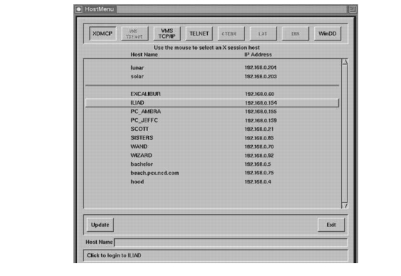
The HostMenu client appears. The HostMenu is designed to allow the user to connect to different types of login hosts, such as Unix or Windows NT.
If you want to use xdm to connect to a Unix host, click on the XDMCP button. The NC will broadcast an XDMCP message to all hosts. The hosts that respond to the broadcast message will be listed in the HostMenu. (See Figure 1-10.)
If you want to connect to a Windows NT host running Terminal Server Edition with Citrix MetaFrame, click on the WinDD button. This displays a list of Windows NT servers running Citrix MetaFrame software. Selecting one of these hosts will display the local WinDD ICA client with a login window.
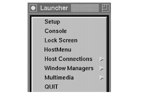
Starting a Session with Launcher
Client Launcher is used to start local clients by selecting a client from a menu. An arrow to the right of a Client Launcher entry indicates a submenu that contains additional local clients. As shown in Figure 1-11, selecting Host Connections displays a submenu listing available connections, such as Telnet or the WinDD ICA Client.
Press the SHIFT-Pause key to bring up the Client Launcher. The symbol in the left margin indicates a Launcher menu selection. If the Launcher is not present, press the SHIFT-Pause key or key sequence for your keyboard.
Table 1-2 Key Sequences for Displaying the Client Launcher
- You can customize the Launcher client for your users through the system.launcher file. Refer to the Using the Client Launcher section in Chapter 4, Local Clients.
Opening a Telnet Session
Telnet provides a direct connection from the network computer to a host computer. When Telnet is running, the network computer acts as a standard VT102 terminal.
To open a Telnet session from Launcher:
- Position the pointer on the Host Connections option to display the submenu. Select Telnet to open a Telnet window as Figure 1-12 shows.
- Use the mouse to position the pointer in the Telnet window. Type h and press Enter to see a list of Telnet commands.
- Type:
- Telnet> open hostname
- where hostname is the name or network address of the host as Figure 1-13 shows.
- Once a connection is made you can log in as Figure 1-14 shows.
- At the login: prompt, enter your user name:
- When the password: prompt appears, enter your password:
- Set the display environment variable for the network computer by entering the following using the network computer's IP address:
- If you run a window manager, type your normal command line. In this example, we are starting the Motif Window Manager.
Closing a Telnet Window
To close the Telnet window from the Telnet> prompt, type quit and press Enter. When you are ready to conclude the Telnet session, log off your host:
then enter quit to close the Telnet window:
Using Setup
Setup is a utility where you can add, modify, display, and save network parameters. Parameters can be saved in NVRAM, or written to a file.
The Setup main menu is illustrated in Figure 1-15. The Setup main menu is made up of four different areas: Menu Bar, Menu Input, Function Bar, and Message Box.
Note: The Setup window on your network computer may look different from this example based on your network computer model. To connect to a Unix host, use the following procedures to enter configuration parameters using Setup. After each typed entry, press Enter.
- Drag in the Configuration Summaries menu and release on TCP/IP.
- Drag in the Configuration Summaries menu and release on
X Environment.- Drag in the Network Tables and Utilities menu and release on NFS Mount. Click on Add Table Entry.
Note: Only four entries may be saved into NVRAM.
- File System Name exported directory
Local Directory local_directory
Transfer Size read size for transferring filesExiting Setup
When you are ready to exit Setup, click the Exit Setup button.
This completes the basic network computer installation process. Continue in Chapter 2, Making Choices, where you will develop a centralized administration scheme for a complete network computer installation.