

Using Advanced Features
This chapter provides information about these advanced NCBridge software features:
- Audio Player for recording and playing audio files on the network computer.
- Audio Mixer for controlling the audio volume for the line in and microphone on the network computer.
- Digital Video Player for playing NTSC or PAL video sources on the network computer.
- Analog Video Player for playing analog video sources on the network computer.
- WinDD to run Windows NT applications on a PC server.
- Font Caching for storing fonts in your network computer's memory.
- Printing Color Hardcopies from your network computer.
- TekLogin Local Client to simplify login and application access.
- PPP Support for network connections via serial lines (phone lines).
- Screen Saver Support that enables you to display .gif images.
- 16-Bit Plane True Color Support for better visual effects.
- Web-Based Administrator
- Seriald for Remote COM Support from Windows NT Applications.
Table 5-1 shows the advanced features provided on the XP, NC200, NC400, and NC900 NCBridge models.
Audio Player
The Audio Player plays and records digital audio files. When started, the Audio Player displays as shown in Figure 5-1.
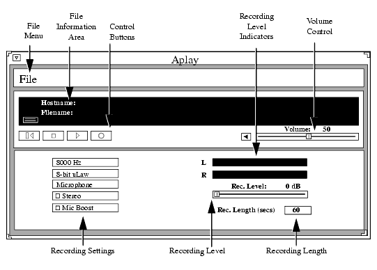
The player can play files that have these extensions:
- .au Sun file type
- .wav Microsoft file type
- .voc Sound Blaster file type (play only)
- .aiff Macintosh file type
- .snd Macintosh file type
- .raw no file header
If a file does not have an extension, the player attempts to read its header information. If there is no header information, the player plays it as a headerless file (.raw).
The Audio Player supports the file formats 8-bit linear, 8-bit uLaw, 8-bit aLaw, and 16-bit linear (LSB & MSB).
The following topics present information about using the Audio Player:
- Starting the Audio Player on page 5-4 provides information about the various ways to start the Audio Player
- Opening or Creating an Audio File on page 5-9 provides information about opening and creating audio files
- Connecting External Audio Devices on page 5-17 provides information about the types of external devices that can be used with recording audio files
- Recording an Audio File on page 5-21 provides the steps for recording an audio file
- Playing an Audio File on page 5-23 provides the steps for playing an existing audio file
- Audio File Information on page 5-24 provides information about obtaining original audio file recording information
Starting the Audio Player
The Audio Player can be started from the Client Launcher, from the remote configuration file, or with the xpsh command.
>>> CAUTION Before connecting any audio device to the network computer (such as microphones or headsets), close all clients, remote connections, and power down the network computer. Connecting devices to the network computer's audio connectors with power applied could result in a loss of data. After the devices are connected, start the Audio Player.
Starting the Audio Player from the Client Launcher
From the Multimedia submenu, select Audio Player. Figure 5-1 shows the Audio Player.
Starting the Audio Player from the Remote Configuration File
The start AUDIO_PLAYER command in the remote configuration file (xp.cnf) automatically downloads and starts the Audio Player when the network computer boots. Refer to the start command in Chapter 2 of the NCBridge Reference Manual for details.
Starting the Audio Player with xpsh
xpsh can start the Audio Player client, shown in Figure 5-1, or can simply play an audio file without opening the Audio Player. To start the Audio Player with xpsh, enter:
The following options can be set on the xpsh command-line:
-h host specifies the host name or address on which the audio file resides. The host must be entered in the network computer's Internet Host Table in Setup. This host displays in the Audio Player's File Information area.
-f filename and path specifies the audio file name and its entire path. This file displays in the Audio Player's File Information area.
-a access method specifies the access method used to access the audio file. Available access methods are tftp, nfs, and dap.
-v volume level specifies the volume level to use when playing the audio file. Specify a number between 0 and 100, with 0 indicating no volume, and 100 indicating the loudest volume setting.
-p when used with the -h, -f, -a, and -v options, the specified file plays without opening the Audio Player. The entire file plays and cannot be interrupted.
-propcmd enables the "property command" interface, which allows other clients to send command strings to control the aplay client remotely. (See the examples that follow.)
-title "string" assigns a title for the aplay window.
Examples
This example starts the Audio Player on the network computer named sierra:
This example starts the Audio Player with the host portland and the audio file
/usr/adam/story.au preloaded in the Audio Player's File Information Area:This example plays the audio file /usr/adam/story.au (located on the host portland) on the network computer without opening the Audio Player:
The first xpsh example above starts the aplay client on a network computer named sierra; the second starts the Audio Player with the host eugene and the audio file /usr/adam/story.au preloaded in the Audio Player's File Information Area; and the third example plays the audio file /usr/adam/story.au (located on the host eugene) on the network computer without opening the Audio Player.
Property Command Interface
The property command interface lets other clients remotely control the command-line version of the aplay client by allowing these other clients access to four "properties" created by the aplay client on the X server. (See Table 5-1, Audio Player Properties.) If the aplay client is executed with the -propcmd option, atoms (which uniquely identify each property) are created and become associated with these character strings. The aplay client's shell window ID is then assigned to the _TEK_APLAY_WID property.
To use these properties to control the aplay client, get the value of _TEK_APLAY_WID. You will need to know the client's window ID when setting the value of _TEK_APLAY_CMD, getting the value of _TEK_APLAY_REPLY, and finding the status of _TEK_APLAY_STATUS.
Commands that can be sent to the aplay client via the _TEK_APLAY_CMD are of two types: value-free and valued.
Value-free commands. A value-free command is simply a request for an action to be performed. Value-free commands include: PLAY, STOP, PAUSE, REWIND, and MUTE.
Valued commands. A valued command sends a command and a value to be used in the performance of that command. Valued commands include: FILE, VOLUME, ACCESS, and HOST. Valued commands can be used to set a value, or to query the client for a value.
The format for setting a value is:
There is no white space separating the command, colon, or value. The value is different depending on the command. The FILE command requires a full absolute path to a file.
Valued commands can also be used to query a particular value. This is done by sending the command and getting the string associated with the _TEK_APLAY_REPLY property. If the command string FILE is loaded into the _TEK_APLAY_CMD property, the current file name is stored in the _TEK_APLAY_REPLY property. If the command string VOLUME is loaded into the _TEK_APLAY_CMD property, the current volume level is stored into the reply property.
Once the aplay client gets notification that the _TEK_APLAY_CMD property has changed, it gets the command string associated with it and deletes the property value. This is an acknowledgment that the aplay client has handled the property command.
To find the status of the aplay client, simply check the string associated with the _TEK_APLAY_STATUS property. The value of status is either STARTED, PAUSED, or EOF.
Opening or Creating an Audio File
The Open command on the File menu creates a new file to record, or opens an existing file.
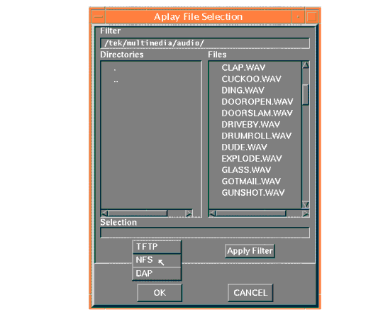
- Select the Open command from the File menu. The File Selection window appears as shown in Figure 5-2.
- To select the access method to use, position the mouse pointer on the NFS button and click. A drop down menu displays the available methods: TFTP, NFS, or DAP. The File Selection window changes to reflect the chosen access method.
Using TFTP Access
The TFTP File Selection window shown in Figure 5-3 displays when TFTP is the access method:
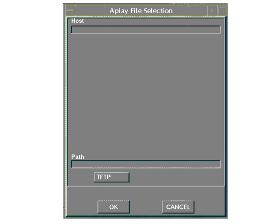
Note: Use TFTP as the access method only if NFS is not available. NFS provides better and more accurate data transfer rates required to maintain continuous audio stream. If using TFTP as the access method, the Audio Player cannot play a file that is greater than 16MB. If you attempt to play a file larger than 16MB, the player will ignore the file.
Creating a New Audio File Using TFTP Access
When creating a new audio file using TFTP as the file access, the file must exist and have world-write permissions before the audio data can be written to it. In addition, only the .au, and .raw file extensions can be used with TFTP.
- Create the new audio file and give it world-read and -write permissions.
- Enter the Host name or address on which the file will be stored in the Host field.
- Enter the filename, path, and extension in the Path field. Use only the .au (Sun file type) or .raw (no header) file extensions.
- Click on OK to open the file. The Host and file names display in the File Information Area.
Opening an Existing Audio File Using TFTP Access
- Enter the name or address of the Host on which the file is located in the Host field.
- Enter the file's path, filename, and extension in the Path field. Files with the following extensions can be played on the Audio Player:
- .au Sun file type
- .wav Microsoft file type
- .voc Sound Blaster file type
- .aiff Macintosh file type
- .snd Macintosh file type
- .raw no file header
When opening an existing file, you can choose the Info command to see the file's original recording information. Refer to the Info command later in this chapter for more information.
Using NFS Access
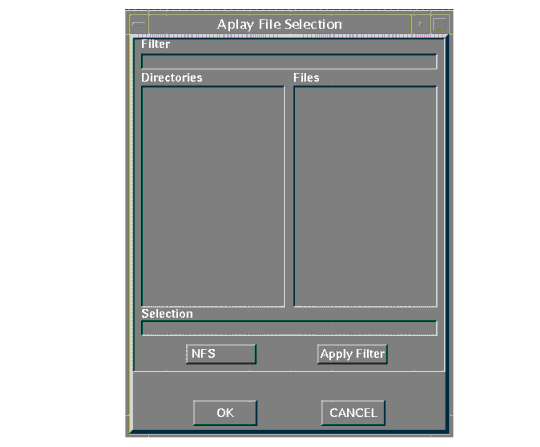
Figure 5-4 displays the NFS File Selection Window when NFS is the access method.
Creating a New Audio File Using NFS Access
When using NFS as the file access, an NFS mount must be established to the Host on which the file resides and must have world-read and -write access.
- Enter the local NFS mount point to the network computer in the Filter field.
- Enter the full path, filename, and extension in the Selection field. The following file extensions are available:
- .au Sun file type
- .wav Microsoft file type
- .aiff Macintosh file type
- .snd Macintosh file type
- .raw no file header
- If no extension is given, the file is recorded as a headerless file (.raw).
Opening an Existing Audio File Using NFS Access
- Enter the NFS mount point in the Filter field.
- Click on the Apply Filter button. All subdirectories and files are listed in the Directories and Files areas.
- To view files in a different directory, click on the directory name in the Directories area, and then click on the Apply Filter button. The files in that directory are listed in the Files area.
- Select the file you want in the Files area. The full path and filename prefills in the Selection field. Enter one of these file extensions:
- .au Sun file type
- .wav Microsoft file type
- .voc Sound Blaster file type
- .aiff Macintosh file type
- .snd Macintosh file type
- .raw no file header
When opening an existing file, you can choose the Info command to see the file's original recording information. Refer to the Info command later in this chapter for more information.
Using DAP Access
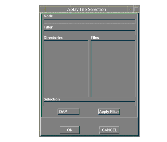
The following File Selection window displays when DAP is the access method.
Creating a New Audio File Using DAP Access
- Enter the node name or address in the Node field. This is the node on which the file will be stored.
- Enter the full path, filename, and extension in the Selection field. The following file extensions are available:
- .au Sun file type
- .wav Microsoft file type
- .aiff Macintosh file type
- .snd Macintosh file type
- .raw no file header
- If no extension is given, the file is recorded as a headerless file (.raw).
Opening an Existing Audio File Using DAP Access
- Enter the node name or address in the Node field. This is the node on which the file is located.
- Enter the file's path and directory in the Filter field.
- Click on the Apply Filter button. All subdirectories and files are listed in the Directories and Files areas.
- To view files in a different directory, click on the directory name in the Directories area, and then click on the Apply Filter button. The files in that directory are listed in the Files area.
- Select the file you want in the Files area. The full path and filename prefills in the Selection field. Enter one of the following file extensions:
- .au Sun file type
- .wav Microsoft file type
- .voc Sound Blaster file type
- .aiff Macintosh file type
- .snd Macintosh file type
- .raw no file header
When opening an existing file, you can choose the Info command to see the file's original recording information. Refer to the Info command later in this chapter for more information.
Connecting External Audio Devices
- Figure 5-6 shows the audio input and output connectors for the XP, NC200, and NC400 series. All of the jacks accept a 3.5 mm phone plug.

The NC900 provides two 3.5 mm audio connectors, one for microphone in and one for speaker out as shown in Figure 5-7.
 >>> CAUTION: Before connecting any audio device to the network computer, close all clients, remote connections, and power down the network computer. Connecting devices to the network computer's audio connectors with power applied could result in a loss of data.
Self-biased microphones such as an electret condenser microphone have an internal battery and a two conductor plug. These are compatible with the XP, NC200, NC400, and NC900 series.
The NC900 supports dynamic, electret condenser (self-biased), and the newer PC99-type microphones.
- A line level signal from a stereo audio source such as an audio mixer, pre-amplifier, compact disc player, or tape player, plugs into the line-in jack. NC900 models use the
symbol to identify the line-in/microphone jack, while XP, NC200, and NC400 models employ the
symbol to show the line-in jack.
- The line-out jack provides a line-level stereo signal for use by a mixer, pre-amplifier, tape player, or other equipment that can accept a line level input. This output provides the highest quality audio. NC900 models use the
symbol to denote the line-out/headphone jack, while XP, NC200, and NC400 models use the
symbol to indicate the line-out jack.
- The headphone jacks on NC200, NC400, and NC900 models work with stereo headphones and 32
powered stereo speaker sets. The XP series supports 8
unpowered and powered speaker sets. Inserting the headphone plug into this jack disables the internal monitor speaker.
Audio Accessory Specifications for XP, NC200, and NC400 Series
The following specifications can assist you when choosing accessories to use with the Audio board.
Microphone Specifications
- Microphone Type · Dynamic
- · Electret (or condenser) with integrated battery
- Impedance Medium to High (600 to 1000
at 1 kHz)
- Sensitivity -55 to -70 db (at 1 kHz)
- Frequency Range 50 Hz to 16 kHz
- Cord Length 6 feet or longer (for ergonomic reasons)
- Plug 3.5 mm monaural phone plug
Line Input Specifications
- Signal Level 0.775 Vrms nominal
- Input Impedance High (greater than 20 K
)
- Plug 3.5 mm stereo phone plug
Line Output Specifications
- Signal Level 0.775 Vrms into a 600
load
- Plug 3.5 mm stereo phone plug
Speaker/Headphone Specifications
- Impedance 8
(minimum) on XP only
- 32
(minimum) on NC200, NC400)
- Plug 3.5 mm stereo phone plug
Audio Accessory Specifications for NC900 Series
The following specifications can assist you when choosing accessories to use with the Audio board.
Microphone Specifications
- Microphone Type · Dynamic
- · Electret (or condenser) with integrated battery
- · PC99-compatible
- Impedance Medium to High (600 to 1000
at 1 kHz)
- Sensitivity -55 to -70 db (at 1 kHz)
- Frequency Range 50 Hz to 16 kHz
- Cord Length 6 feet or longer (for ergonomic reasons)
- Plug 3.5 mm monaural phone plug
Line Input Specifications (same jack as microphone)
- Signal Level 0.775 Vrms nominal
- Input Impedance High (greater than 20 K
)
- Plug 3.5 mm stereo phone plug
Line Output Speaker/Headphone Specifications
- Signal Level 0.775 Vrms into a 600
load
- Plug 3.5 mm stereo phone plug
- Impedance 32
(minimum)
Recording an Audio File
The Audio Player works much like a home stereo. It has a Record button, a Stop button, and a Play button. It also has a number of recording settings you can adjust so that the audio file is recorded for the type of device on which it will be played. Audio files can be played on almost any computer that has audio capabilities, including network computers, personal computers, and workstations.
When a new file is created, the default file settings reflect the device on which it will be recorded, in this case, the network computer.
If an existing file is opened, the settings displayed in the Audio Player reflect the settings at which the file was recorded if the network computer can support the settings. If not, the Audio Player adjusts the settings to best match the network computer's capabilities. To see the exact settings at which the audio file was recorded, select the Info command in the File menu.
Before recording, attach any external audio devices. Refer to the Connecting External Audio Devices topic on page 5-17.
Before recording, set the recording options listed here:
- Frequency Select a sampling frequency. The higher the frequency, the clearer the recording. The available frequency settings are limited to the network computer hardware. You cannot record at a frequency higher than the network computer supports. If you try to record at an unsupported frequency, a warning displays.
- File Format Select a file format. The File Format determines how the audio file is stored.
- Input Source Select the input source of the audio data: microphone, stereo line, video line, or a mix of multiple sources. Refer to the Audio Mixer for information about mixing input sources. Refer to the Using the Audio Mixer topic on page 5-26 for details about the Audio Mixer.
- Stereo This option toggles the stereo option. Select this option to record in Stereo, or de-select it to record in mono.
- Mic Boost This option toggles the Microphone boost option. Select this option to increase the sensitivity of the microphone.
- Recording Levels Sets and shows the recording level. Slide the recording level indicator to the right to increase the levels. The Left and Right feedback area shows the decibel levels during recording. If the levels reach the "red area", indicated by red bars, the recording may be at too high a level. Slide the recording indicator to the left to reduce the recording level.
- Recording Length Sets a maximum recording time limit (up to 999999 seconds). Use this option if you want to control the length of the recording. When the recording reaches the time limit, the player automatically stops recording.
After setting the recording options, you are ready to record:
To make recording adjustments, change any of the recording options and go back to Step 2. Repeat this procedure as needed.
Playing an Audio File
The Audio Player can play files that have these extensions:
- .au Sun file type
- .wav Microsoft file type
- .voc Sound Blaster file type
- .aiff Macintosh file type
- .snd Macintosh file type
- .raw no file header
- Files that do not have an extension are played as raw files.
- Use the Open command on the File menu to open the audio file. When the file is opened, use the Info command on the File menu to view the recording settings. These settings may differ from the settings displayed on the Audio Player. The Audio Player settings reflect the current hardware capabilities. The original recording settings may not be available on the hardware, so the Audio Player automatically adjusts the settings to best match those that are available with the hardware.
Click the Play button.
Audio File Information
After opening a file that already exists, use the Info command on the File menu to display a window with the file's original recording information. Figure 5-8 shows how the filename, frequency, format, channel, and duration information are displayed.

When opening an existing file, the options displayed on the Audio Player reflect the current hardware capabilities. The original recording settings may not be available on the hardware, so the Audio Player automatically adjusts the settings to best match those that are available with the hardware.
To close the File Information window, click the CANCEL button.
Closing the Audio Player
To close the Audio Player, select the Quit command from the File menu. Any open file information is saved and the player exits.
Audio Mixer
The Audio Mixer allows you to control the hardware volume for line in, microphone, and prerecorded (digital) sources. You are not required to use the Audio Mixer when recording or playing audio or video files. When started, the Audio Mixer displays as shown here:

The Audio Mixer is like a master volume control, much like the volume control on a home stereo receiver. The volume control on the stereo receiver controls the output volume for all the stereo components, such as the tape player and the CD player. Likewise, the mixer controls the input and output gain for the Line In, Digital, and Microphone sources.
Note: The Bell Gain control is available on NC900 models only. Each volume control has a toggle Sound button. When clicked on, the sound is heard. When off, the sound is muted until it is selected again. This allows you to quickly mute the sound and then to resume.
Starting the Audio Mixer
The Audio Mixer can be started from the Client Launcher, from the remote configuration file, or with the xpsh command.
Starting the Audio Mixer from the Client Launcher
From the Multimedia submenu, select Audio Mixer. The software displays the Audio Mixer as shown in Figure 5-9.
Starting the Audio Mixer from the Remote Configuration File
The start AUDIO_MIXER command in the remote configuration file (xp.cnf) can be used to automatically download and start the Audio Mixer when the network computer boots. Refer to the start command in Chapter 2 of the NCBridge Reference Manual for details.
Starting the Audio Mixer with xpsh
xpsh can open the Audio Mixer client, as shown in Figure 5-9. To open the Audio Mixer with xpsh, enter this command:
Using the Audio Mixer
To use the Audio Mixer to monitor input, adjust the volume levels of the Line In Gain, Digital Gain, and the Microphone Gain, depending on what you are using as the input source(s).
- When playing an audio file, the Audio Mixer sets the output levels for each of the input sources relative to each other.
- When recording an audio file, the Audio Mixer sets the recording levels of the input sources relative to all of the input sources. The combined input sources, except the microphone input, are then recorded as a single source (mixed).
Examples of Using the Audio Mixer
Below are some common examples of using the Audio Mixer.
- You can play a compact disc through the network computer's speaker (Line In) and use the Audio Mixer to control the volume.
- When recording an audio file using the Audio Player, you can open the Audio Mixer client and adjust the Line In Gain volume so that you can monitor the file as it records. (Note, you are not required to use the Audio Mixer when recording an audio file.)
- To selectively record specific segments of an audio source, adjust the Audio Player so that it is ready to record, open the Audio Mixer, and begin playing the audio source. When a segment plays that you want, start recording. When finished, stop the recording while still listening to the audio source. When another segment starts that you want to record, begin recording again. This allows you to selectively record only what you want without having to start and stop the audio source.
- To record multiple inputs on NC200 and NC400 models, set the input source on the Audio Player to Mixed. The Audio Mixer controls the recording volume of each of the input sources. For example, to record sound from several input sources to go with a presentation, such as the Digital Video Player and a CD player, set the Line In Gain to a lower level than the Digital Video. (The Line In Gain controls the CD volume and the Digital Video gain controls the recording volume of video soundtracks.) Set the recording settings on the Audio Player, start recording the music, start the Vplay client, and then adjust its volume level. When finished, stop the recording and play back the audio file. If necessary, readjust the levels on the Audio Mixer and re-record until the relative gains are correctly set.
- NC900 models employ one input jack for both line-in and microphone gain, so it is not possible to record multiple inputs on NC900 models. If you click the Microphone Mute control, the Line In Gain control is no longer available; it is automatically muted. Conversely, clicking the Line Gain control on the Audio Mixer dialog toggles you to the Line Gain control and the Microphone Gain control is muted.
Keep in mind that after the relative gains for the input sources are set with the Audio Mixer, you can then use the Recording Level feature on the Audio Player to adjust the multiple sources as a single source at a higher or lower level.
Saving the Audio Mixer Level Settings
To save the level settings from one Audio Mixer session to another, note the dB values for the Line In Gain, Digital Gain, and Microphone Gain and add them to the start AUDIO_SERVER command in the xp.cnf remote configuration file. The next time the Audio Mixer starts, the dB values are preset.
Closing the Audio Mixer
To close the Audio Mixer, select the Quit command from the File menu.
Digital Video Player
The Digital Video player allows you to play video files in a video window on your network computer. An optional digital video coprocessor card, available only on the XP400, NC200, and NC400, is required to support this feature. The video file must be in MPEG1 file format. When started, the Video Player displays as shown in Figure 5-10.
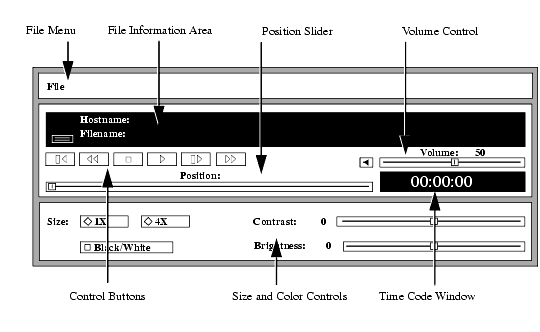
The following information about the Video Player is available:
- Starting the Video Player provides information about the various ways of starting the Video Player.
- Opening a Video File provides information about opening video files.
- Using the Video Player provides the steps for playing video files.
- Multicast provides information about sending packets from a single point to multiple receivers.
Starting the Video Player
The video player can be started from the Client Launcher, from the remote configuration file, or with xpsh.
Starting the Video Player from the Client Launcher
From the Multimedia submenu, select Digital Video. The Video Player displays as shown in Figure 5-10.
Starting the Video Player from the Remote Configuration File
The start DIGITAL_VIDEO command in the xp.cnf remote configuration file can be used to automatically download and start the Video Player when the network computer boots. Refer to the start command in Chapter 2 of the NCBridge Reference Manual for details.
Starting the Video Player with xpsh
xpsh can start the Video Player client, as shown in Figure 5-10. To open the Video Player with xpsh, enter this command:
The following vplay options can be set on the xpsh command-line:
- -h (Host) specifies the Host name or address on which the video file resides. The Host must be entered in the network computer's Internet Host Table in Setup. This host displays in the Video Player's File Information area.
- -f (Filename and path) specifies the video file name and its entire path. This file displays in the Video Player's File Information area.
- -a (Access method) specifies the access method used to access the video file. Available access methods are tftp, nfs, dap and multicast. NFS is the preferred file access method for faster and more accurate data transfer rates required by the player. In addition, there is a 16MB limit on files transferred with TFTP.
- -v (Volume level) specifies the volume level to use when playing the video file. Specify a number between 0 and 100, with 0 indicating no volume, and 100 indicating the loudest volume setting.
- -m (Mute) specifies that the video file plays with no sound.
- -c (Color) specifies that the video file displays in color (used only if the video was recorded in color).
- -nc (No Color) specifies that the video file displays in greyscale images.
- -b (Big) specifies that the video file displays in a frame four times the size of the original file.
- -p (Play only) When used with the -h, -f, -a, and -v options, the specified file plays without showing the Video Player. The entire file plays and cannot be interrupted.
- -all (Play All; software player only) plays all frames in a video file. Frame scheduling is ignored and the audio will not be in sync.
- -title "string" assigns a title for the vplay windows.
- -propcmd creates properties that allow other clients to send command strings to the Video Player. These properties can be used to control the Video Player from another client. For details about the properties, see the vplay man page.
- -brightness n sets the brightness level of the video file. Specify a number between -50 and +50.
- -contrast n sets the contrast level of the video file. Specify a number between -50 and +50.
- -BUFSIZE n (Hardware player only) specifies the size of the Video Player's memory buffer (in kilobytes). The value defaults to 1024 and can not be set lower than 1kilobyte. If the value specified is greater than available memory when trying to play a file, the Video Player reduces its buffer to the available memory.
- -CHKSIZE n (Hardware player only) specifies that the Video Player's memory buffer is divided into "chunks", measured in kilobytes. The network fills the chunks, and the Video Player empties them as they are accessed. The default is 32, which divides the buffer into 32 kilobyte chunks. If the chunk size is set to a number larger than the buffer size, the chunk size will be truncated to one half the buffer size. The chunk size cannot be set less than 1 kilobyte.
- -CHKDELAY n (Hardware player only) specifies the time delay (in milliseconds) that the Video Player waits following each read request that fills a chunk.
Examples
This example opens the Video Player on the network computer named sierra:
This example opens the Video Player with the host portland and the video file
/usr/adam/scene.mpg preloaded in the Video Player's File Information Area:This example plays the video file /usr/adam/scene.mpg (located on the host portland) in color and with no sound on the network computer without showing the Video Player:
Opening a Video File
The Open command on the File menu opens and displays an existing video file. Video files must be in MPEG file format only.
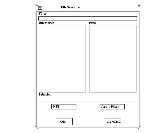
- Select the Open command from the File menu. The File Selection window appears as shown in Figure 5-11
Using TFTP Access
The File Selection window in Figure 5-12 displays when TFTP is the access method.
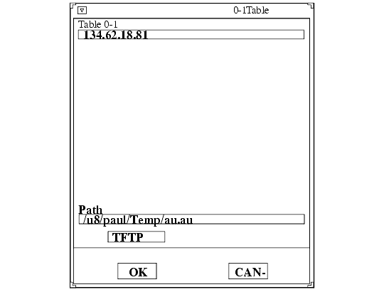
Notes: Use TFTP as the access method only if NFS is not available. NFS provides better and more accurate data transfer rates required to maintain continuous audio and video stream. If using TFTP as the access method, and you attempt to play a file that is greater than 16MB of MPEG data, the Digital Video Player ignores the remaining data after 16MB has been reached.
In addition, inherent limitations in TFTP prevent fast forward and fast rewind from being supported.
Using NFS Access
The File Selection window displays when NFS is the access method.
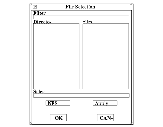
To use the File Selection window when NFS is the access method:
- Enter the NFS mount point in the Filter field.
- Click on the Apply Filter button. All subdirectories and files are listed in the Directories and Files areas.
- To view files in a different directory, click on the directory name in the Directories area, and then click on the Apply Filter button. The files in that directory are listed in the Files area.
- Select the file you want in the Files area. The full path and filename prefills in the Selection field. The file must be an MPEG file.
- Click OK. The Host and file names display in the File Information Area.
Using DAP Access
The File Selection window shown here displays when DAP is the access method.
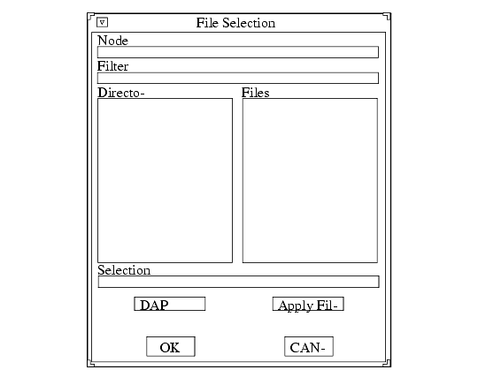
- Enter the node name or address in the Node field. This is the node on which the file is located.
- Enter the file's path and directory in the Filter field.
- Click on the Apply Filter button. All subdirectories and files are listed in the Directories and Files areas.
- To view files in a different directory, click on the directory name in the Directories area, and then click on the Apply Filter button. The files in that directory are listed in the Files area.
- Select the file you want in the Files area. The full path and file name prefills in the Selection field. The file must be an MPEG file.
- Click OK. The Host and file names display in the File Information Area.
Playing a Video File
After opening the video file using the Open command, use the Control Buttons to play the file:
Note: If the file does not play, check the Console for messages. If the file is not an MPEG file format, the console displays the following message: <FileName> is not an mpeg file! If the video file includes audio, the Audio Player must be set to a sample frequency rate of 8000Hz. Otherwise, the audio will not play.
To fast forward through the file, click and hold the Fast Forward button. Release the button when you want to stop. Refer to the Fast Forwarding and Rewinding topic on page 5-39 for more information.
To fast rewind through the file, click and hold the Fast Rewind button. Release the button when you want to stop. Refer to the Fast Forwarding and Rewinding topic on page 5-39 for more information.
To adjust the volume, slide the volume controller to the right to increase the volume, or to the left to decrease the volume. Be sure the Sound button is on, or pushed in. The Sound button acts as a mute toggle; when it is pushed in, you can hear the sound, when it is off, the sound is muted.
While playing the video file, use the following controls to adjust the size and color of the video file.
- Size Plays the video in the size it was recorded (1X), or in a video window four times the size it was recorded (4X).
- Black/White Plays the video in color, or in greyscale. Turn this option on to play the file in black and white, or off to play the file in color.
- Contrast Sets the contrast level. Slide the level indicator to the left to decrease contrast levels, or to the right to increase the contrast levels.
- Brightness Sets brightness level. Slide the level indicator to the left to decrease brightness levels, or to the right to increase the brightness levels.
Fast Forwarding and Rewinding
The Fast Forward and Fast Rewind functions allow you to directly access any part of a video file. By using the Video Player's fast forward and fast rewind buttons or position slider, you can start playback from any location in a file, or replay a portion of a file any number of times, without having to start at the beginning.
Note: The Fast Forward, Fast Rewind, and Position Slider are not available if using TFTP as the file access method. The slider (NFS only) and time-code window let you see how much of a file has already played. The slider represents a time index corresponding to the time code embedded in the MPEG stream. If the stream begins at zero, the time code acts as a simple timer of how long the video is. Whether you use the buttons or slider, the time-code window displays the time code of the current frame location in hours, minutes, and seconds. Both the slider and window are updated dynamically during playback.
To fast forward or fast rewind using the position slider, do the following:
To fast forward or rewind using the Video Player's buttons, do the following:
As you drag the slider or press the fast forward or fast rewind button, the video window is updated, displaying intermediate video portions. When you release the slider or button, the video player returns to its previous state. For example, if a video was playing when you repositioned the slider or pressed the button, the video restarts when you release it. If a video was on pause, it remains on pause.
As mentioned, you can use any mouse button to drag the slider. However, if you click on the first mouse button when the mouse is within the position slider track (but not on the slider button), the slider moves a tiny bit to that side of the slider button, no matter where in the track you place it. Essentially, the video is repositioned to the nearest MPEG Group of Pictures (GOP) boundary (generally about 1/2 second). If you press the second mouse button when it is in the slider track, the file is positioned at that location.
Multicast
Multicast is a way to send packets from a single point to multiple receivers. The receivers can determine when and if they receive the Multicasted packets. Multicast video takes advantage of networks that support Multicasting to decrease network bandwidth and provide a means of easily accessing video information.
The Digital Video player allows you to play video files in a video window on your network computer using Multicast. The video file must be in MPEG file format.
Note: Multicast is only available on XP400, NC200, and NC400 network computers. Channels
Channel changing is an interface that maps "channel" numbers to Multicast addresses. This mapping is made in the xp.cnf remote configuration file and remains fixed until the network computer is rebooted.
Selection of a channel causes the client to cease reception on any current channel and attempt to join a transmission in progress on the selected channel. The client begins reading data from the Multicast IP address. When it reads sufficient data to properly set up the window size, the view window resets its size. A default sized window is started before this happens.
Choosing Multicast Channels
- Edit the video_multicast_entry command-line in the xp.cnf remote configuration file to set your Multicast channel options. (Refer to the video_multicast_entry command in Chapter 2 of the NCBridge Reference Manual.) These channels display on the Video Player's Multicast menu option. If you omit this step, the Video Player does not display the Multicast menu.
- In the Video Player, click on the Multicast menu to display the available channels.
- Select the channel from the Multicast menu. The Video Player starts as soon as something is received on that channel.
Multicast Options
The following Multicast options can be added to the xpsh command-line when starting the Digital Video Player:
Note: Where indicated, the following vplay options apply to both broadcast and Multicast, though in different ways. Only information relevant to Multicasting is included below. -h host specifies the Multicast IP address. This address must be the same as the address being used by the Multicast server. See your system administrator for valid choices.The address displays in the Video Player's Addr/Port Information Area.
-f filename specifies the Multicast port number. This port number must be the same as the port number being used by the Multicast server. See your system administrator for valid choices. The port number displays in the Video Player's Addr/Port Information Area.
-chan n specifies an index into an array of available Multicast channels. (Refer to the Channels topic on page 5-40 and video_multicast_entry in Chapter 2 of the NCBridge Reference Manual.) Do not use with the -h, -f, -a, or -text options.
-text "string" specifies the channel string displayed by the Video Player. Do not use with the -chan option.
-a access method specifies the access method used to access the video file. Use Multicast when Multicasting.
Example
This example starts the Video Player and plays the video being Multicast on IP address 224.200.50.1, port 3000. The Video Player displays the text "The Blues Channel".
The Video Player opens displaying the Multicast menu as shown in Figure 5-15.
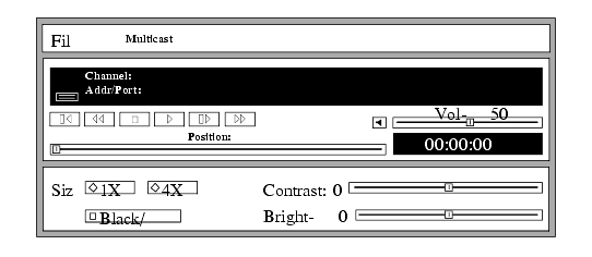
When viewing a Multicast video, the Forward, Fast Forward, Rewind, and Fast Rewind buttons are not operational. However, the time index (displayed in the Time Code Window) shows the current time code within the current video segment of the Multicast video. You can note the video segment number and load it at a later time as a file, reposition to a specific location, and review a segment of the video previously seen during a Multicast session.
Closing the Video Player
To close the Video Player, select the Quit command from the File menu. Any open file information is saved and the player exits.
Analog Video Player
The Analog Video Player enables you to view NTSC (National Television System Committee) or PAL (Phase Alternation Line-rate) sources in a window on the network computer's display (XP300V or X317CVJ only). Common NTSC and PAL video sources are VCR's, video disc players, video cameras, and television tuners. When viewing a video on the network computer, you can control the volume, window size and placement, and color settings. When started the Analog Video Player displays as shown in Figure 5-16.
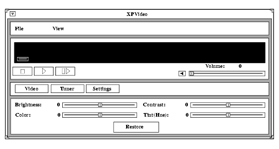
The Analog Video player requires the analog hardware. Not all network computer models have the analog hardware.
Before using the Analog Video Player, the xv server extension must be enabled. If the analog hardware is present, the xv server downloads automatically when the network computer boots. If for some reason the xv server extension is disabled, use the enable_xv command in the remote configuration file to enable it. Refer to Chapter 2, Remote Configuration in the NCBridge Reference Manual for details.
The following information about the Analog Video Player is available:
- The Starting the Analog Video Player topic on page 5-46 provides information about the various ways of starting the Analog Video Player.
- The Connecting the Network Computer to an Analog Video Device topic on page 5-47 provides information about the ports on the network computer and connecting the video device.
- The Using the Analog Video Player topic on page 5-48 provides the steps for viewing analog video sources.
Starting the Analog Video Player
The Analog Video Player can be started from the Client Launcher, from the remote configuration file, or with xpsh.
Starting the Analog Video Player from the Client Launcher
From the Multimedia submenu, select Analog Video. The Analog Video Player displays as shown in Figure 5-16.
Starting the Analog Video Player from the Remote Configuration File
The start ANALOG_VIDEO command in the xp.cnf remote configuration file can be used to automatically download and start the Analog Video Player when the network computer boots. Refer to the start command in Chapter 2 of the NCBridge Reference Manual for details.
Starting the Analog Video Player with xpsh
xpsh can start the Analog Video Player client, as shown in Figure 5-16. To open the Video Player with xpsh, enter the following:
The following options can be set on the xpsh command-line:
- -encode specifies the encoding format. Specify either NTSC, which is commonly used in the United States; or PAL, commonly used in Europe.
- -source specifies the video source to which the video device is connected. Specify either COMPOSITE_1, COMPOSITE_2 or SVIDEO1.
- -color specifies the color intensity of the video being played. Specify a number from -1000 to 1000. 0 is the default.
- -bright specifies the color brightness intensity of the video being played. Specify a number from -1000 to 1000. 0 is the default.
- -contrast specifies the color contrast intensity of the video being played. Specify a number from -1000 to 1000. 0 is the default.
- -tint specifies the color tint of the video being player. Specify a number from -1000 to 1000. 0 is the default.
Connecting the Network Computer to an Analog Video Device
To use the Analog Video Player, first connect the video device to the network computer. The Analog Video Player plays NTSC and PAL video encoded sources.
Note: Refer to your video source user manual for cabling and encoding information. There are several ports on the back panel of the network computer used for analog video. Connect composite sources to the Port 1 Composite, Port 2 Composite, or Port 1 SVideo ports. Refer to Figure 5-17 for the location of the video ports.
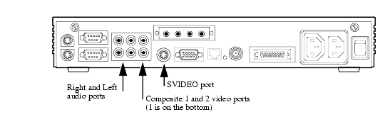
Note: You cannot have two video devices connected to Port 1 Composite and Port 1 SVideo at the same time. Using the Analog Video Player
When the audio device is connected, you are ready to view the video on the network computer. When started, the Analog Video Player displays the video options as shown in Figure 5-18. (The Video button on the player is depressed.)
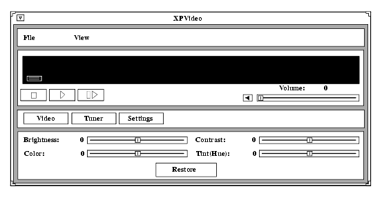
To play a video on the network computer:
- Connect the video source to the network computer. Refer to the Connecting the Network Computer to an Analog Video Device topic on page 5-47.
Click on the Play button. A separate XPVIDEO window displays which is used to view the video. (This does not affect the video source. You must start the video source with its own play function.) The icon below the File menu changes to include a viewer window. If the viewer window is obstructed by other windows, clicking on this icon brings the viewer window to the top.
To adjust the volume, slide the volume controller to the right to increase the volume, or to the left to decrease the volume. Be sure the Sound button is on, or pushed in. The Sound button acts as a mute toggle; when it is pushed in, you can hear the sound, when it is off, the sound is muted.
To freeze a frame, click on the Pause button. This displays the frame in the viewer window; however, it has no effect on the video source which continues to play. Click on the Play button to resume viewing the video source.
While viewing a video, you can control the following window attributes:
- Brightness Sets the brightness level. Slide the level indicator to the left to decrease brightness levels, or to the right to increase the brightness levels.
- Color Sets the color level, or intensity. Slide the level indicator to the left to decrease color intensity, or to the right to increase the color intensity.
- Contrast Sets the contrast level. Slide the level indicator to the left to decrease contrast levels, or to the right to increase the contrast levels.
- Tint/Hue Sets the tint, or hue, levels. Slide the level indicator to the left to decrease the tint/hue levels, or to the right to increase the tint/hue levels.
- Restore Restores the video player options to the default settings.
- View Menu The View Menu contains the ResetSize command. This command returns the viewer window to its default size.
Clicking on the Settings button displays the Settings options as shown in Figure 5-19.
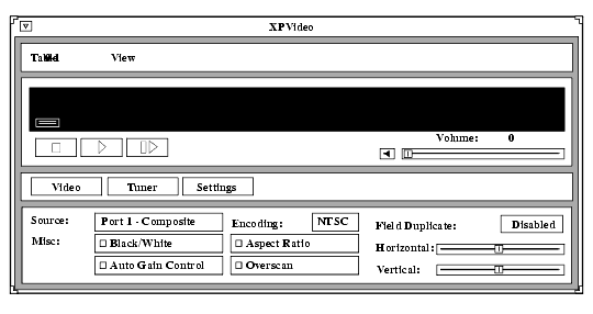
You can change these settings:
- Source specifies the video source to use: Port 1 Composite, Port 2 Composite, or Port 1 SVideo.
- Encoding specifies the encoding format. Specify either NTSC, which is commonly used in the United States; or PAL, commonly used in Europe.
- Black/White specifies whether the image in the viewing window displays in color or in black and white.
- Auto Gain Control specifies the Automatic Gain Control setting. When turned ON, the video signal is automatically amplified for best picture quality.
Note: The Tuner options are not available at this time.
- Aspect Ratio specifies the window sizing attributes. Aspect ratio refers to the relative proportion of the video window's width and height. If you want to maintain this ratio when resizing a window, specify ON for this setting. Then when you change a window size, it is automatically adjusted to preserve the aspect ratio. If OFF, you can resize the window to any size and the aspect ratio is not maintained.
- Overscan specifies whether the image in the viewer window is in overscan mode. If ON, the full image displays. If OFF, the image is reduced by 10% to match the viewing area of typical consumer television screens.
- Field Duplicate specifies whether the Analog Video Player uses field duplication. Field duplication is used primarily to eliminate blurred images when viewing fast motion videos or images generated by graphics systems such as video games. AUTO specifies that the player determines whether to use field duplication based on the video window size.
- Horizontal positions the contents of the view window horizontally. Slide the indicator to the left or right to move the contents of the viewer window left and right.
- Vertical positions the contents of the view window vertically. Slide the indicator to the left or right to move the contents of the viewer window up and down.
- View Menu The View Menu contains the ResetSize command. This command returns the viewer window to its default size.
Closing the Analog Video Player
To close the Analog Video Player, select the Quit command from the File menu.
WinDD ICA Client
The WinDD ICA client provides access to PC servers running Microsoft's Windows NT Terminal Server Edition and Citrix Metaframe software. Once you are logged in to the PC server, you can run Windows NT and DOS based applications.
Starting the Local WinDD ICA Client
The WinDD ICA client can be started using the Client Launcher, TekHostMenu, the remote configuration file, or from the command-line with xpsh.
Starting WinDD from the Client Launcher
From the Host Connections submenu, select WinDD. The WinDD local client is illustrated in Figure 2-14 on page 2-16.
Starting WinDD from TekHostMenu
Click the WinDD button (if necessary) to access the WinDD list. Click on a server, or enter the server name or address in the Application Server box.
Starting WinDD with xp.cnf
The start WINDD command in the xp.cnf remote configuration file automatically downloads and starts WinDD when the network computer boots. Refer to the start command in Chapter 2 of the NCBridge Reference Manual for details. Related WinDD remote configuration commands include:
host_connect_method default_host_list
windd_menu_entry windd_auto_connect
windd_auto_reconnect windd_size
default_windd_host windd_host_entry
windd_menubar windd_entrybox
start preload
flash_feature windd_auto_numlock
windd_keysym_only windd_exit_on_logout
Starting WinDD with xpsh
xpsh starts the WinDD local client as needed. Enter the following (where nc_name is the name or address of your network computer):
- xpsh -display nc_name:0 windd [options]
The following options can be set on the xpsh command-line. If an option is not specified, the default setting is used.
- -display nc:0
specifies the network computer (nc) name or address to display the WinDD local client.- -c means auto-connect to the first application server in the application server list. If there are no application servers in the list, this option is ignored and the client window is displayed.
- -nc means do not auto-connect to an application server. (Default)
- -d displays the menu bar and the internal borders. (Default)
- -nd says do not display the menu bar or the internal borders. For example, this allows a 1280x1024 WinDD window to fully display on a 1280x1024 monitor (minus windows manager decorations).
- -e enables the Application Server edit field window so that users can add application servers to the application server list. (Default)
- -ne disables the Application Server edit field window so that users are not allowed to add application servers to the application server list.
- -floppy
allows supported host versions of WinDD to use its local floppy drive as a network connected drive for the application server. Only the first host client to specify this option will be allowed to use the floppy device. NOTE: For host clients (with local floppy drive) only.- -no_floppy_cache
disables use of local floppy write cache. This is a fail-safe option to ensure the entire file has been updated in the event a user suddenly ejects a disk mechanically (when disks are ejected via the GUI button, that process flushes the cache so no information is lost).- -geometry <geometry>
means use the standard X11 geometry option, <WidthxHeight+X+Y>.- -h <application server>
adds the named application server(s) to the application server list. Multiple application servers can be added to the list by listing them separated by spaces.- -help
displays a brief help list on the available WinDD command-line options.- -initprog <prog> [-initdir <dir>]
specifies the application to execute upon application server login. The login session is terminated when the application is terminated.- Prog specifies the application and can also specify its path (up to 259 characters) and parameters. The program path and name are written consecutively (and not separated by a space) when they are both specified in prog. A space separates the program name and its parameters. These parameters are program specific and can specify program settings or data files to invoke on execution.
- Dir specifies the path of the executable program.
- -keysym_only
specifies that all NCD network computer keyboards are supported with keysym translations within WinDD.- -local_numlock
specifies that WinDD manages the state of the Num_Lock independent of any Xserver support.- -no_auto_numlock
specifies that WinDD does not control the Num_Lock setting.- -login <username> [-pass <passwd>] [-domain <domainname>]
specifies the application server user account login name, login password, and domain. These values will be used for user account verification.- When using a WinDD client and connecting to an application server, your username, password, domain, initial program, and initial directory are encrypted as they are sent across the network.
- Username, password, domainname, dir, and prog are not viewable or changeable from the WinDD configuration window.
- -r means reconnect to the application server after log off.
- -nr says do not reconnect to the application server after log off. (Default)
- -version
displays the WinDD version in use. (If the license is 8019, this option also prints For evaluation purposes only.)- -x exits the WinDD client upon logging out of, or disconnecting from, the application server.
- -nx means do not exit the WinDD client upon logging out of, or disconnecting from, the application server. (Default)
- -force_xcursor
specifies that monochrome pointers within the WinDD desktop are to be implemented using X cursors. Some monochrome pointers are xor'd with the underlying desktop. When this switch is specified, it is no longer xor'd, as X cursors do not support that mode.
- -compress
enables compression of ICA network data to and from the WinDD client.- -no_compress
disables compression of ICA network data to and from the WinDD client.- -max_compress_disable
disables compression for n number of outgoing ICA commands from the WinDD client. The default is 0, which enables all compression. A count setting of 0 might "compress" client data larger than its original size during start of login session. Settings larger than 0 restrict expansion of the client data.- -a published_app
allows an ICA session to connect to any published application on a WinFrame/MetaFrame-based server. The argument published_app is the name of the published application.xp.cnf Compression Commands
Configuring your WinDD ICA Session from the Client Screen
From the WinDD ICA client screen shown in Figure 5-20, you can easily change your session attributes before you log in to a server.
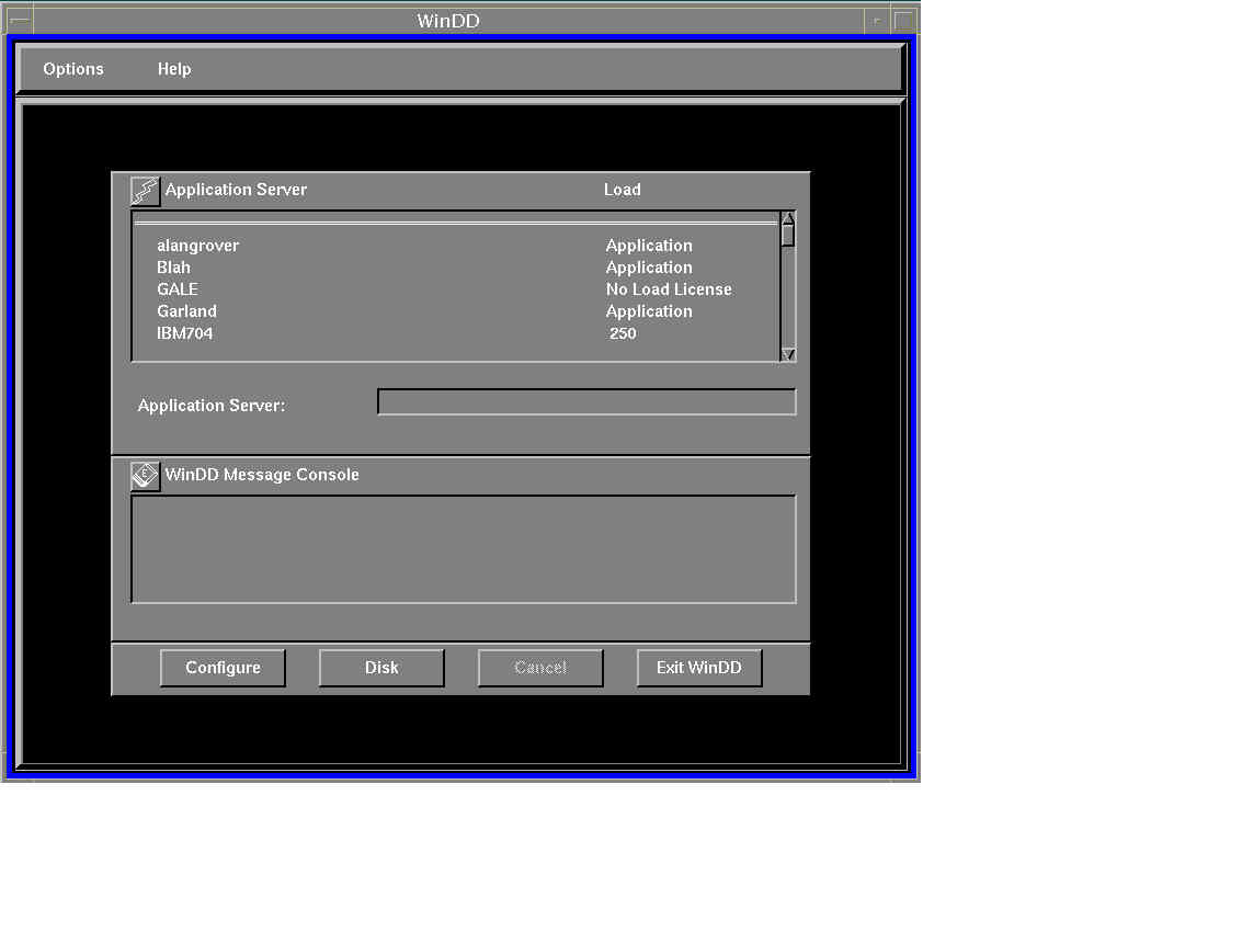
The Configure button brings up the WinDD Configuration dialog illustrated in Figure 5-21. The resolution determines the size of the WinDD window. The resolution must be selected prior to making a connection to the application server and cannot be interactively changed until the connection has been closed. The Configure button performs the same function as the Options > Configure pull down menu choice.
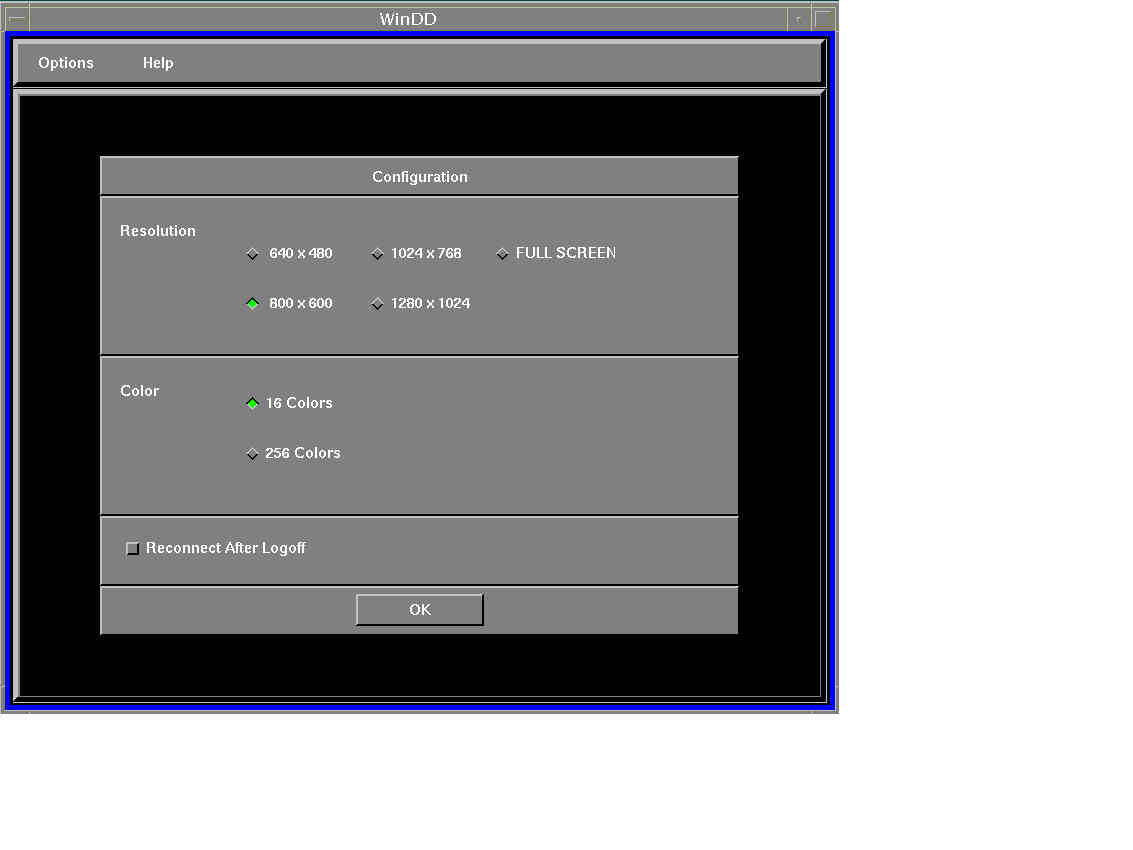
The Reconnect After Logoff button enables automatic reconnection to the application server after you have logged off of a WinDD session. If this button is on, then the WinDD log in screen (see Figure 2-16 on page 2-20) appears when you select File > Logoff from a Windows NT 3.51 session or Start > Logoff on a Windows NT 4.0 or later session. If this button is off, the WinDD client screen is displayed when you log off a session.
WinDD messages about connection status, error conditions, or other necessary user feedback appear in the message console area. All message are also sent to the network computer system console so that the information is available even if WinDD has been terminated. Use the Clear Console button to clear messages.
When configuration is complete, select the application server for your session.
Selecting an Application Server
The WinDD ICA client screen displays a list of application servers your system administration defined for you. Use the mouse to select one of the servers from the list. If the application server you want to access is not on the list, enter the name or address in the Application Server: field and press Enter. WinDD log- in information is in Chapter 2, Operating the Network Computer.
WinDD Local Client Options Menu
There are two ways to access the local client Options menu:
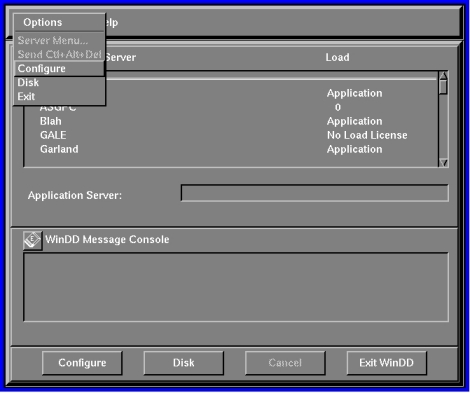
- Select Options from the local client menu bar shown in Figure 5-22.
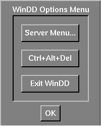
- Hold down Shift and Ctrl and click the middle mouse button shown in Figure 5-23. This method is only available after you have a server connection.
Log On
Toggles between the WinDD session window and the WinDD ICA client screen. This is only available after you have a server connection. The Cancel button on the client screen returns you to the session window.
Configure
Brings up the WinDD Configuration dialog shown in Figure 5-21. This is only available before you have a server connection.
Exit
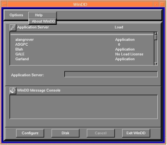
WinDD Help Menu
The WinDD Help Menu presents WinDD copyright and version information.
Font Caching
The font caching feature stores fonts in memory for later use. This eliminates the need to download a font each time the application using the font is executed. For example, if you open and close your word processor, then open it again, the fonts are still available if your network computer's memory. This is a more efficient use of resources, since fonts are cached once, instead of duplicated for each occurrence or downloaded over a busy network.
You can specify the amount of memory to allocate or you can flush cached fonts at any time. It is recommended that cache be flushed whenever new fonts (with a font path change) are added, to insure that the proper paths are cached. Flushing does not affect the current applications.
Select Setup from the Client Launcher.
- Check the amount of memory in your network computer by dragging on Statistics and releasing on Memory.
- Drag on Configuration Summaries and release on X Environment.
- Set Font Cache Limit to the amount of memory in kilobytes to allow for font caching. Do not exceed the total memory for your network computer.
To empty the Font Cache and free up network computer memory:
Printing Color Hardcopies
This section explains how to print a hardcopy by using the MWM pop-up menu item or by entering a command on the command-line. Information in this section is specific to the MWM. If you are using another window manager, refer to the documentation you received with that window manager for more information about printing a hardcopy.
Note: The host computer must have the appropriate software installed before you can use these hardcopy commands. If you cannot print a hardcopy, contact your system administrator. Printing from MWM
You can use a pop-up menu to make a hardcopy of a window or a hardcopy of the entire screen.
Making a Hardcopy of a Window
- Move the pointer outside of all windows and drag the Custom mouse button to display the pull-down menu.
- Release on Hardcopy to display another pull-down menu.
- Click the Custom mouse button on Window to change the pointer shape into a cross.
- Move the pointer into the window you want to copy.
- Click the Select mouse button. A single beep indicates the window is being copied. A double beep indicates the copying process is complete.
Making a Hardcopy of the Screen
- Move the pointer outside of all windows and drag the custom mouse button to display the pull-down menu.
- Release on Hardcopy to display another pull-down menu.
- Click the custom mouse button on Screen. A single beep indicates the screen is being copied. A double beep indicates the copying process is complete.
Printing from the Command-Line
Here is a general procedure for printing a hardcopy of a window:
TekLogin Local Client
Many customers want to present their end-users a simplified environment with simple login methods and easy access to applications. The new TekLogin local client adds one more piece to that end, streamlining the login process and allowing system administrators to decide how much or how little control to offer their end-users.
The TekLogin local client is commonly used with the PPP support feature (refer to the PPP Support topic on page 5-68) to provide remote users access to host servers.
Starting TekLogin
There are several ways to launch the TekLogin client. You can launch it with:
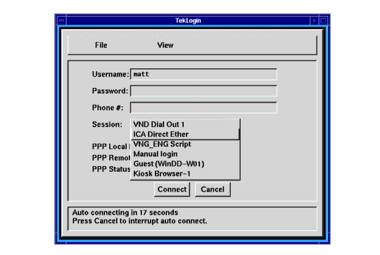
As noted in the previous section, you can choose TekLogin as your Host Connect Method in Setup's Configuration Summaries > X Environment menu. After a successful boot, the network computer will display the TekLogin client, as seen in Figure 5-25 on page 5-65.
Another method is to set Launcher to display and launch the TekLogin client. You can manually edit your system.launcher file to do this or set this line in your xp.cnf file to YES as shown here:
This will automatically display all eight of your pre-configured sessions in a pull-down menu in the Launcher.
A third way to start TekLogin is with the xpsh command:
Finally, you can have TekLogin start automatically with the xp.cnf file by un-commenting and altering this line in your xp.cnf file:
Change the value for this line to YES.
xp.cnf Commands for TekLogin
You can add these commands to your xp.cnf file to affect the TekLogin client. Refer to your NCBridge Reference Manual for details about these commands.
The first two commands listed are notable in that they are not configurable with the TekLogin client itself, as most of the others are. The teklogin_show_sessions_in_launcher command will display the configured sessions in the Launcher client as pull-down selections. The teklogin_force_fullscreen_windd command forces the WinDD ICA client launched by TekLogin to take up the whole screen (rather than a 640x480 window, the default).
Configuring TekLogin Settings
In the File pull-down menu, you can select Save Settings, Restore Settings, or Exit.
- Save Settings This saves the current user name, password, phone number, and session settings such that the next time the TekLogin client is launched, these settings will display.
- Restore Settings Restores the last saved settings.
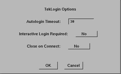
In the View pull-down menu, you can select Setup or Options. Both of these selections will require a password if you set password restriction in the Setup main menu.
- Setup This launches the Setup client. System administrators can disable this feature if they do not wish end-users to have access to the Setup client. (See the Security Between TekLogin and Setup topic on page 5-67 for details.)
- Options Autologin Timeout. The default timeout is 30 seconds, after which, if the user does not click the Cancel button, TekLogin will attempt to make the connection described by the session name. If the user cancels the autologin, he can then choose one of the other configured sessions in TekLogin by its session name. The autologin defaults to the last session connected to via TekLogin.
- Interactive Login Required. This requires the user to enter his username and password after the PPP authentication has occurred.
- Close on Connect. If TekLogin is not configured to close on connect (default), it will remain on the user's screen, allowing the user a simple method of disconnecting from one session and reconnecting to another. Some system administrators may wish to disable this functionality, forcing the network computer to connect using only session configuration.
Security Between TekLogin and Setup
System administrators can set the security mechanism for a network computer in Setup's main menu so that no user can tamper with the network computer's configuration without the password. The security is activated whenever a user enters something in Setup or presses a button. Some of the fields, however--such as username and password for both authentication and account login purposes--need to be alterable to end-users. With security activated on the Setup client, users will be able to enter their own user names and passwords, but will not be able to change the session names or other configuration parameters.
If security is enabled, the TekLogin client will not launch the Setup client, so system administrators can effectively "hide" Setup from novice users.
PPP Support
PPP is a reliable transparent Internet Protocol (IP) that allows network computers to make network connections via serial lines to remote devices. NCBridge's PPP passes TCP/IP information over the phone line in such a way that it appears as though your network computer has an Ethernet connection.
PPP support is available for the following devices:
Before You Begin
To run PPP successfully, you will need both the local PPP client process that runs on the network computer and the PPP server that runs on the remote host computer. NCBridge version 3.1 or higher software provides the PPP client; you will need to get the appropriate PPP server software from your host vendor.
There are several different ways you can connect your network computer via PPP to a remote host, but before you begin, you must first configure:
Configuring the Network Computer's Serial Port
Before you can connect via PPP, you must configure one of your network computer's serial ports for your modem.
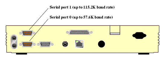
First, select a port on the rear panel of your network computer. Since many users may already have tablets or other peripheral devices connected to port 0, and since port 1 allows higher transmission rates (115.2K), we recommend you use port 1 for your modem connection, especially if you are using ISDN lines. On the NCD network computers, port 1 is the upper port; port 0 is the lower. Connect your modem's 9-pin female cable to the desired port. (All examples in this section assume port 1 has been configured for PPP.)
After you have connected the modem cable to your serial port, you must configure the serial port for modem transmission. In Setup, go to Configuration Summaries > Peripheral Ports. (See Figure 5-28 on page 5-70.)
The fields in the lower half of this menu (from Network-to-Port Process down) do not affect your modem, so we will ignore them here. We are concerned with one of the two columns at the top, depending on the port you have chosen. For our example, this is Serial Port 1, on the right.
The "8", "1", and "None" default settings for the first three fields (Data Bits, Stop Bits, and Parity) will be correct for virtually all current production modems. (Check your modem user documentation to be sure.) The Flow Control and Baud Rate settings are really the only two you will need to configure.
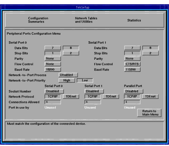
Flow Control. This field determines what kind of PPP "handshake" passes between the network computer and the server: None, XON/XOFF, or CTS/RTS.
Baud Rate. This refers to your modem's transmission speed. We recommend setting this field to at least 57,600 to avoid starving the modem of data. Port 0 supports a maximum of 57,600 baud rate; Port 1 supports up to 115,200.
Configuring the Network Computer's Session/PPP Settings
Next, you will have to configure your network computer's session and/or PPP settings. In Setup, go to Configuration Summaries > Session. This menu allows you to configure the network computer for PPP sessions and for Ethernet sessions.
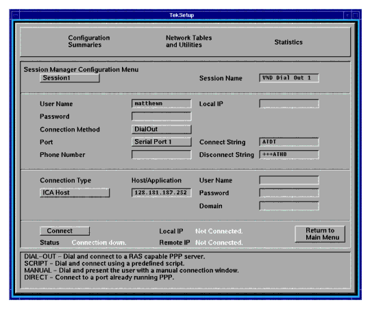
As you can see in Figure 5-29, the Session Manager Configuration Menu is divided into four areas, known as identification, authentication, connection, and status.
Session Identification
In this area, identify each of up to eight session configurations.
Session. You can specify one of eight sessions in this field. For each session, you will configure the settings in the other fields listed below. When you select one of the eight sessions with this button, the settings you configure in the other fields described below will appear.
Session Name. Give each of your eight sessions a distinguishing name that will help users identify the correct session for their needs.
Session Authentication
The session authentication area is for authentication purposes. Each session requires some form of authentication to make the session connection.
User Name. You must provide a valid user name.
Password. You must provide a valid password. Your password will appear as asterisks as you type it in; the field itself will appear blank after you press Enter. These two authentication parameters (User Name and Password) are saved in NVRAM when you click the Save Settings to NVRAM button.
Connection Method. There are four choices: Dial Out, Direct, Manual, Script.
- Dial Out The dial out method--probably the most common--can only be used to connect to RAS servers (or servers emulating the RAS interface). Dial Out assumes PPP is already running on the Host.
- Direct This refers to a true direct serial cable connection from one device (your network computer) to another (an NT server, for example), in which the baud rate on the two devices' serial ports must be the same. We recommend you use this method only when you have a null-modem serial cable connecting your network computer directly to a server.
- Manual This selection automatically brings up a TIP window and forces the user to enter his/her username and password. If the PPP daemon is not running on the Host, the user will also have to start it manually.
- Script This allows you to specify a script to automate the authentication process.
- Port Select Serial Port 0 (PPP), Serial Port 1 (PPP), or Ethernet.
- Serial Port 0 (PPP) Select this if you have configured Serial Port 0 for PPP (up to a maximum of 57,600 baud rate).
- Serial Port 1 (PPP) Select this if you have configured Serial Port 1 for PPP (up to a maximum of 115,200 baud rate).
- Ethernet This selection disables all the PPP settings you may have configured in the Session Configuration Menu and connects directly through the network computer's Ethernet cable.
Local IP. By default, this field is disabled. Any attempt by the user to add an IP address or other string will be ignored. In the rare case when you wish to use this field, you will have to uncomment this line in your xp.cnf file and add an IP address value:
If you do this, be sure to enter a valid unassigned IP address on the same subnet as your server in the Local IP field; if you enter an invalid address, the Host will not allow you to log in.
The remaining fields in the session authentication area may or may not appear, depending on the Connection Method you select. For example, if you choose Direct, you will not need to provide values for the next four fields.
- Phone Number. You must provide a valid phone number for the network computer to dial out to if you select Dial Out, Script, or Manual. This field will not appear if you select Direct as your connection method.
- Script. If you leave this field empty, it will remain blank but will default to one of the supplied scripts. You can also specify another script or one of your own. Enter the name of the script in this field. This field will not appear if you select Direct, Dial Out, or Manual as your connection method.
- Connect String. You must provide a connect string only if you select Dial Out. This field will not appear if you select Direct, Script, or Manual as your connection method. This string is modem vendor-dependent. The default value (shown in Figure 5-29 on page 5-72) works with all Hayes-compatible modems. If you wish to alter the default string, or if it conflicts with your modem, consult your modem user manual for details.
- Disconnect String. (Same information as for the Connect String above.)
Session Connection
The session connection area is for your login connection after you have successfully passed PPP authentication.
- Connection Type. There are several connection types you can choose from.
- None (Default.) None means that after the network computer has made the connection and been authenticated, the user will have to start his own session, launch clients manually, etc.
- ICA Host This selection will connect you to a WinDD/Windows NT host over an ICA connection. If you select ICA Host, you must specify a WinDD/Windows NT host (name or IP address) in the Host/Application field. Unless you specify an alternate configuration in your xp.cnf file, the default WinDD window (640x480, 16 colors) will appear. (Also, see the note below.)
- ICA Application This yields a result similar to the ICA Host connection type, except that the user, instead of getting an entire Windows NT session, will only get access to the specified application. If you select ICA Application, you must specify a (case-sensitive) application name in the Host/Application field. This application name is the name a master ICA browser broadcasts over the network to ICA clients. When you select ICA Application, the master ICA browser will connect you to the Windows NT host that can best serve you that application, based on the server's resources, number of users currently logged in, etc. (Also, see note below.)
- TekHostMenu This will launch the TekHostMenu client, allowing the user to choose amongst the various protocol/host combinations to make a post-authentication connection.
- XDM Direct This sends an XDMCP login from a specific host to the user's display immediately after PPP authentication.
- Telnet This launches a Telnet session to the selected Host.
- Navio This selection is not supported at this time.
Host/Application. This field is for one of two values: You can enter the IP address (or server name) of the ICA host to which the user will login; or the specific published application name. The published application name defaults to the local subnet, but you can optionally prepend the published name with a Windows NT server name or IP address, or with the subnet mask that points to a specific Application Master Browser location as shown, for example, in this entry:
This points to an Application Master Browser on the subnet 192.168.15.255. In such a case, the Application Master Browser selects the Notepad application from among the Hosts on the subnet based on server load.
User Name. Optional. This user name differs from the user name required in the session authentication area of this menu. This user name refers to the actual account the user must have on the server on which he wishes to login; the former user name is for authentication only. If this field is left empty, the user will have to manually login to the server after the session has been authenticated and established.
Password. Optional. This too differs from the password required in the session authentication area. If this field is left empty, the user will have to manually enter his/her password to login.
Domain. Optional. This is only for Windows NT environments. If you have entered a user name and password in the two previous fields, you might also want to specify a Windows NT domain on the login Host. Otherwise, the user will have to manually select a domain at the Windows NT login prompt.
Session status
The session status area is where you make and break session connections. It also displays information about your connection.
Connect/Disconnect. Use this button to make and break your session connections. (See the PPP Connections topic on page 5-80.)
Status. This gives PPP connection status information (terminated, connecting, connected, etc.). If you have selected Ethernet as your Port, Status will display "Connection Down."
Local IP. Local IP refers to the IP address the PPP server allocates to your network computer after the PPP connection has been established. If you have selected Ethernet as your Port, Local IP will display "Not Connected."
Remote IP. Remote IP refers to the IP address of the PPP server you are connected to. If you have selected Ethernet as your Port, Remote IP will display "Not Connected."
Configuring the xp.cnf File for PPP
Configuring the xp.cnf file will allow remote users to make PPP connections automatically, after they boot their network computers. You will need to complete the previous Setup configurations for each network computer you want to connect automatically. You will also need to uncomment and alter this line in your xp.cnf file:
Change the value for this line to YES.
Final Network Computer Configuration Considerations
There are three other menu items in Setup that you should check before you are ready to make a PPP connection.
First, verify that your network computer has an Internet Host name. In Setup, go to Configuration Summaries > TCP/IP. If the first field on this menu is blank, enter a network computer name. If your network computer does not have a name, PPP will generate a unique name for you--based on your network computer's Ethernet address--so it is not critical that you enter one here; it is merely good practice.
Second, there are a few settings in Configuration Summaries > X Environment you should check. If you plan to use either the ICA Host or ICA Application connection type described in the previous section, make sure the Default Visual is set to "PseudoColor" and the Root Depth is set to "8". Also, with NCBridge 3.2 (or higher), there are additional methods (under Host Connect Method) you can use to connect to a Host computer (see Figure 5-30 on page 5-79).
TekLogin, a new local client which allows a simple connection automatically or with a single button-click, is explained in more detail in the TekLogin Local Client topic on page 5-64. You may want to change this setting for your network computer(s).
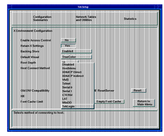
Finally, you might want to save your settings so that you won't have to go through these procedures again the next time you reboot. To do this, click the Return to Main Menu button, then click the Save Settings to NVRAM button on the bottom left of the Setup main menu.
PPP Connections
After you have configured your network computer's serial port, PPP, and other settings, and have attached a modem to one of your network computer's serial ports, you can connect to a remote Host via PPP by using:
Connecting Via TekLogin
TekLogin is a new local client that simplifies the connection process, not just for PPP connections, but for other Host connections as well. This method is recommended, especially in environments where the system administrator wishes to simplify the login procedure for inexperienced users. See the TekLogin Local Client topic on page 5-64 for more information.
Connecting Via Setup
Another way to start PPP is from Setup where the user can see the PPP status and, in case PPP exits, the reason for the connection failure. When PPP comes up, the user will see the IP address for the connection on the network computer (if the remote is assigning IP addresses) and the remote IP address.
For each of the following methods, in Setup, go to Configuration Summaries > PPP and click the Connect/Disconnect button to make your PPP authentication connection, then follow the rest of these procedures below.
Dial out and Direct
For a properly configured Dial Out or Direct session, no other steps are necessary to connect.
Manual
When you click the Connect button for a Manual session, one of the provided scripts (start_man) will start, launching a TIP window and dialing the number specified in the Session Manager Configuration Menu. The start_man script prompts you for your username and password. If the PPP daemon is not running on the Host, you will have to start it manually. The TIP window closes automatically as soon as the script detects that PPP is running on the Host. Otherwise, the TIP window remains open for 30 minutes before closing.
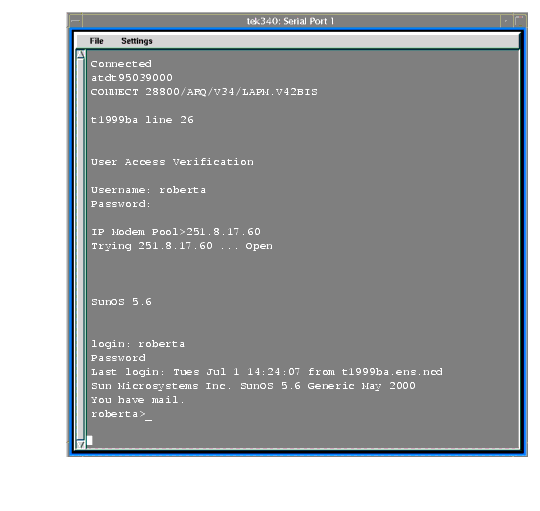
When your connection has been fully established, the remote device assigns you a remote IP address and displays it in the Remote IP field in Setup's Session Manager Configuration Menu.
Script
When you choose to connect via a script, the value you enter in the Script field names the parameter listed in Setup's Network Tables and Utilities > Script Parameters. (See Figure 5-32 on page 5-83.) NCBridge 3.2 (or higher) ships with three sample scripts (start_ppp, start_man, and start_isp) found in the /tekxp/boot/config/script directory. The first of these is the default script when you select Script as your connection method in the Session Manager Configuration Menu; the second starts when you select Manual; the third is included only as an example. You may use these scripts or create your own.
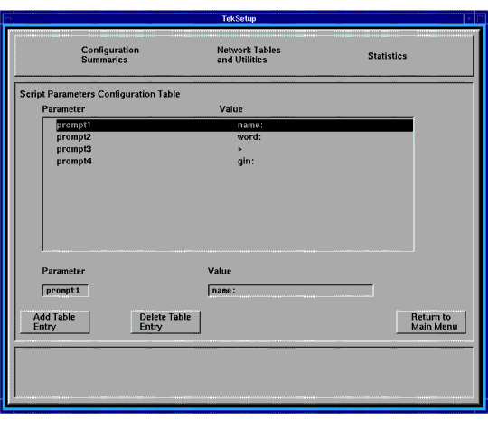
Connecting Via xpsh
While it might not make sense to connect via PPP through the xpsh command (which requires you to be connected to another server in the first place), it is still possible to do so with this command:
Connecting Via the xp.cnf File
If the system administrator has set up the PPP parameters in the xp.cnf file for remote network computer users, the PPP session starts automatically after the network computer boot.
Terminating PPP
With TekLogin, click the Disconnect button on the main menu. In Setup, go to Configuration Summaries > PPP and click Disconnect.
Note: When clicking the Disconnect button, PPP does not send the disconnect string to the serial port to reset the modem. When this occurs, turn off/on your modem to reset the modem. Screen Saver Support
Kiosk administrators can use the screen saver support feature. NCBridge version 3.1 or higher provides a local client ssadvt that allows a customer to display a series of gif images as a screen saver on the network computer. Rather than having the network computer screen simply blank after a specified period of inactivity, system administrators can now display advertisements, corporate-endorsed images, and other images of general interest on inactive network computers. In non-kiosk systems, system administrators can implement the screen saver over an entire network, so that all network computers display the same images.
You can use xp.cnf or the xpsh command to start the screen saver local client ssadvt. Once started for a network computer, you cannot kill or override the process without rebooting the network computer.
Starting the Screen Saver with the xp.cnf File
To start the ssadvt client using xp.cnf, add a line similar to this one to your xp.cnf file:
...where -t indicates the timeout in seconds, -c indicates the cycle time in seconds, and -f indicates the NFS-mounted file with the list of gif images to be displayed.
In this example, when the network computer has been inactive for a period equal to ten minutes (600 seconds), the screen saver displays the first image in the file /home/ssadvt.list. After a minute, the next image in the file is displayed, and so on until the end of the file is reached, then it loops to the beginning and starts over. If a user "interrupts" the stream of screen saver images, for example by moving the mouse, the screen saver resumes with the next image in the list during a subsequent ten-minute period of inactivity.
!Do not delete this line.
/local/GIFS/dilbert11.gif
/local/GIFS/subliminal3.gif
/local/GIFS/csun.gif
/local/GIFS/xena17.gif
/local/GIFS/brainwash.gif
/local/GIFS/pointy-hair.gif
The images in the ssadvt.list file must be .gif files; no other image format is supported. If you include a non-.gif image in the file, that image does not display. The console should mention the status of opening the file ssadvt.list and start displaying a different gif every minute.
Starting the Screen Saver with the xpsh Command
To start the ssadvt client using xpsh, enter this command:
The default method value is nfs, and since no other method is available at this time, the -access argument can be omitted entirely; the default timeout value is ten minutes (-t 600) with a minimum value of 20 seconds; the default cycle time is one minute (-c 60).
16-Bit True Color Support
Note: 16-bit true color support is available only on NC200, NC400, and NC900 models. NC200 and NC400 network computers with option V2 (or field kit NCFV2) provides a total of 4MB of video memory. With 4MB of video memory, these units can take advantage of NCBridge's 16-bit plane true color support. The NC900 comes standard with 4MB of video RAM to support 16-bit true color.
When a network computer is configured to operate in 16-bit plane mode, its X server exports a 16-bit plane TrueColor or DirectColor visual, so your application can display 65,536 colors instead of only 256 colors in 8-bit plane mode. That means you will see markedly better visual effects on applications that can take advantage of 16-bit color depth. Running your network computer in 16-bit plane mode will also eliminate irksome color flashes that occur when multiple color-intensive applications run simultaneously.
Configuration
You can configure a NC200, NC400, or NC900 network computer to operate in this mode either through the Setup client or through the remote configuration xp.cnf file.
In the Setup client, go to the Configuration Summaries > X Environment menu and select "16" for the Root Depth field. Then go back to the main menu and reset the X server by clicking on the Reset Server button. Once the server is reset, it will operate in16-bit plane mode. If you decide to go back to the 8-bit plane mode, reset the Root Depth field to "8" and click the Reset Server button again for 8-bit plane PseudoColor. If you want the network computer to retain the new root depth settings the next time it is booted, click the Save Settings to NVRAM button in Setup's main menu.
To configure the X server to operate either in 8-bit plane or 16-bit plane mode remotely, add this line to your xp.cnf file:
Limitations
There are some limitations with 16-bit plane mode. For one, the WinDD ICA client requires 8-bit PseudoColor and cannot be used in 16-bit plane mode. If you try to launch a WinDD ICA client in 16-bit plane mode, the ICA client writes a message to the console stating that it "cannot find the PseudoColor visual" and then exits. (WinDD X Support works fine in 16-bit plane mode.)
Another limitation is that the digital video player vplay cannot be used in 16-bit mode, due to the fact that current software reserves a color index from the PseudoColor table for the chromakey that makes vplay work.
All local clients except WinDD ICA and vplay work in 16-bit mode.
Web-Based Administrator
The Web-based Administrator allows a system administrator the ability to view a network computer's setup parameters using a standard Internet browser, like Netscape Navigator. If a network computer parameter is set incorrectly, the administrator can identify the problem from his own desktop and change the parameter to the appropriate value without having to visit the user's desk.
Implementation
Using the start command in the xp.cnf file, start the network computer's local HTTP server. Here is an example:
After you put this command in the xp.cnf file, reboot the terminal for it to take effect.
When a browser points to the network computer's IP address, the network computer provides its setup parameters.
Note: A password may be defined for security reasons in the xp.cnf file so that other users may not view or change a network computer's setup parameters. To Access the Web-Based Administrator
Seriald Provides Remote COM Support for Windows NT Applications
Seriald is a local daemon that executes on the network computer. It provides the ability for a Windows NT application to transmit and receive data to and from a peripheral device connected to a remote network computer serial port. Typical peripheral devices include printers, credit card readers, and PalmPilots. Figure 5-34 shows how peripheral devices, Windows NT servers running NCD ThinPATH Plus, and network computers running Seriald are connected.
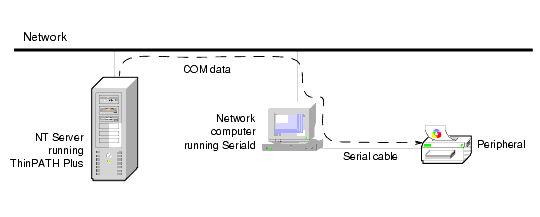
Seriald interacts with the ThinPATH Plus software, which runs under Windows NT 4.0, Terminal Server Edition (TSE). ThinPATH Plus adds suppport for peripheral devices such as local printers.
For example, as an NT application transmits data to a standard COM port, ThinPATH Plus intercepts the data and redirects it to the network computer located on the network. Upon receiving the data, the Seriald daemon passes the data on to the network computer serial port where the peripheral device is connected.
Seriald provides several benefits. For example, Seriald makes it possible for an unmodified NT application to interact with a peripheral device connected to a remote network computer serial port. Seriald also provides the ability to synchronize the data on a PalmPilot with an application executing on an NT server.
By default, Seriald automatically starts when the network computer boots (restarts). You can use these two xp.cnf commands to control the Seriald daemon:
Refer to the NCBridge Reference Manual for details on how the xp.cnf commands work.
For more information about the ThinPATH Plus software, see the Network Computing Devices, Inc. (NCD) website, www.ncd.com, under Products.